Thursday, January 29, 2015

Trackwork Begins

Trackwork has begun on the layout. The first step was to blot together the two modules with 3/8" bolt/nut/washer combos.


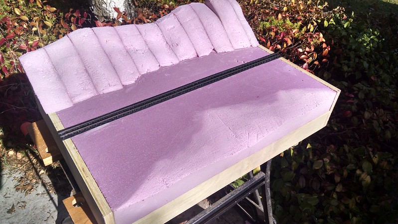
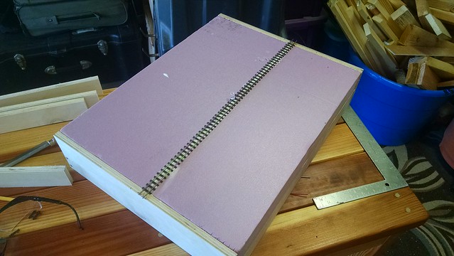
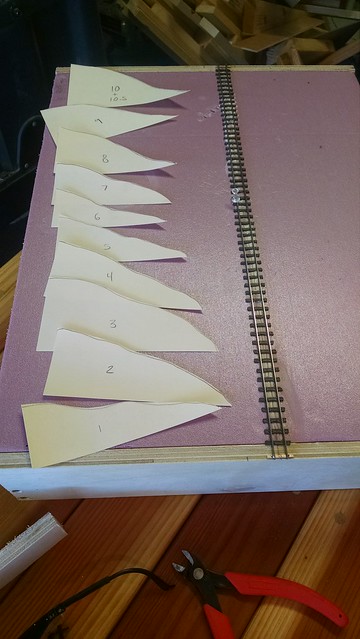
I used a full-sized printout of the plan to locate the main features of the track on the benchwork. Usually, the best method for me is to locate the position of turnouts and tangent (straight) track, and "connect the dots, so to speak.

It seemed most logical to start with the biggest "cluster" of turnouts. I am using Liquid Nails for Projects to cement the track in place, taking care not to foul the pointwork of the turnouts.


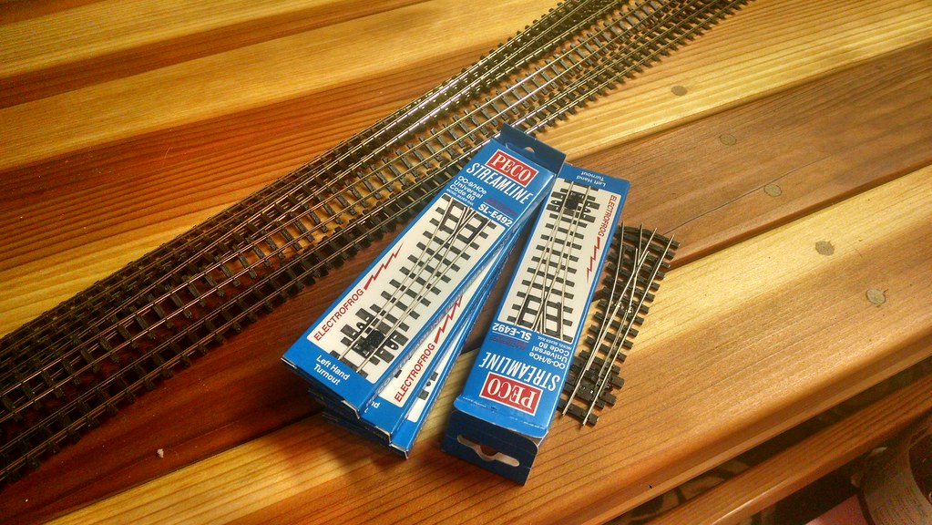
The Peco "electrofrog" turnouts require special considerations in the form of insulating rail joiners, since they route power polarity directly through the frog. I'm interpreting the directions in the clearest way I can, and have my fingers crossed that I'm getting it right!

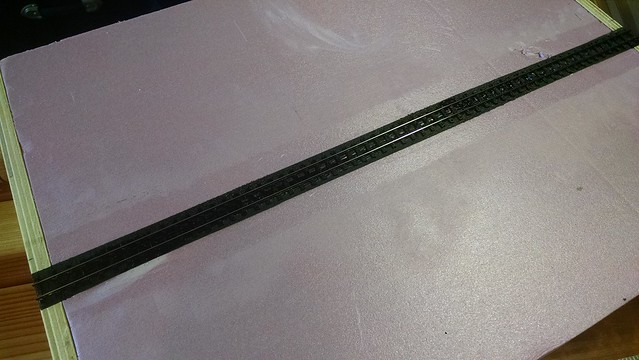
After a couple hours of careful measuring and trimming, the "center stage" trackwork is taking shape.


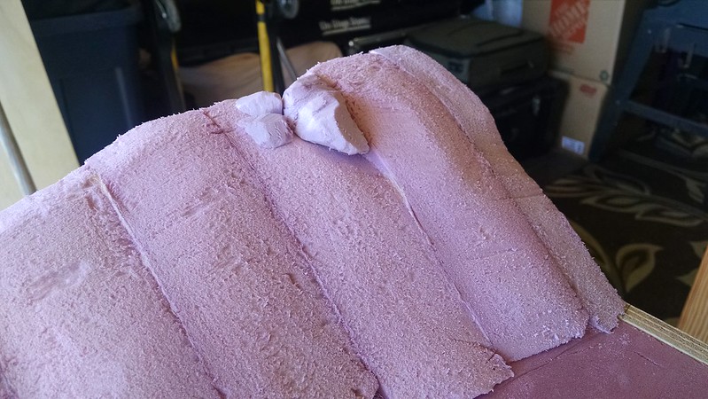
Using experience from past layouts, I'm taking care to ensure smooth transitions through curves.

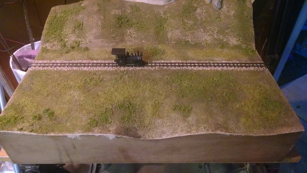
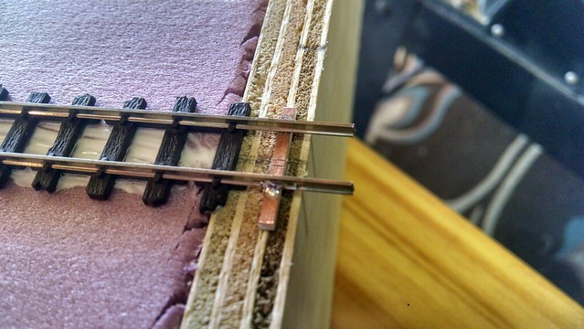
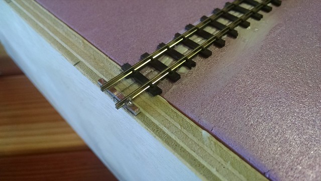
I cemented down the PCB ties that will anchor the rails between the two "modules" that make up this layout. I don't anticipate actually cutting the gaps anytime soon; but this will be a "failsafe" for when I need to separate the modules for a future move/layout transportation.


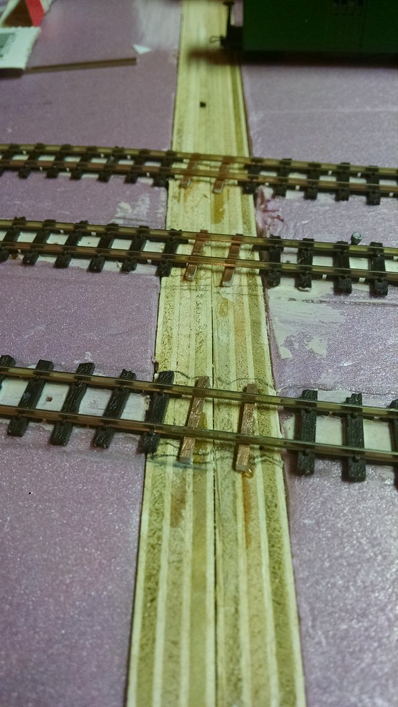
Once the ACC cures, I will solder the rails permanently to the PCB ties. 

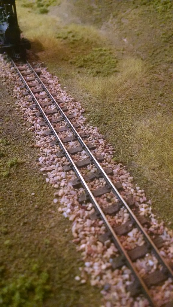
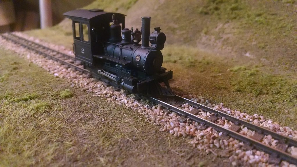
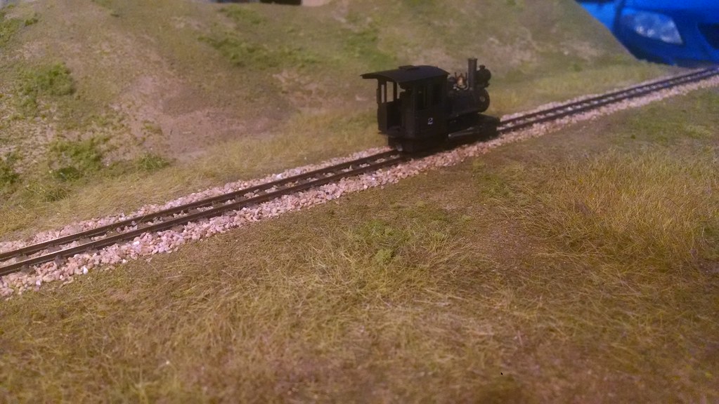
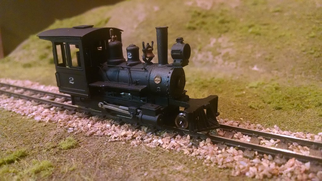
The MVRR's official "test car" rolled a few trial passes down the completed trackwork.


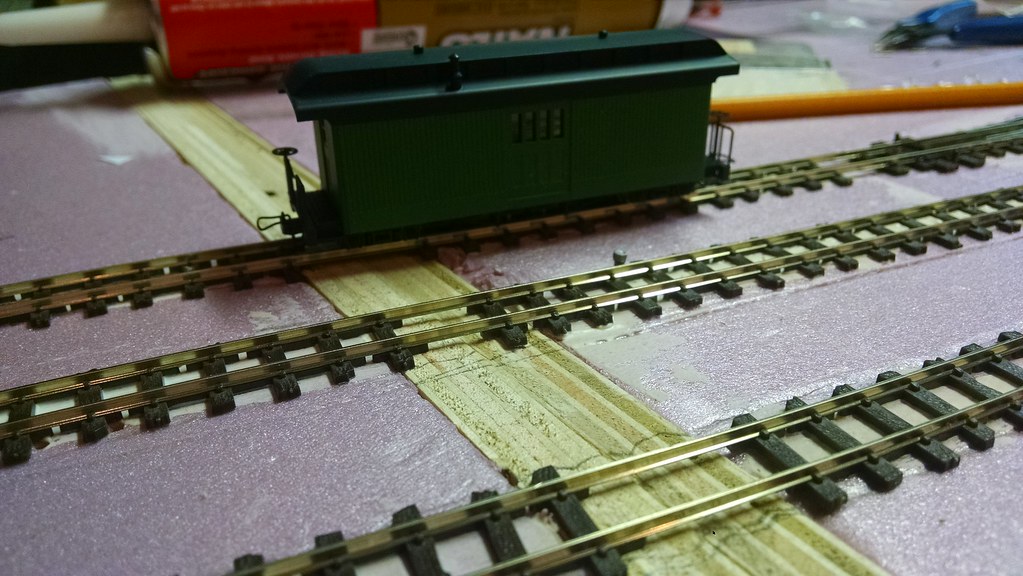
It's exciting to see this incarnation of the Marmion Valley taking shape. After a couple more work sessions, I should have the layout ready for the first "test run," and that will be very cool to see.

Piece by piece, I am steadily growing my roster of HOn30 rolling stock. Currently on the workbench:

- A pair of Marsh Creek Miniatures "Maine Frame" flatcars (resin kits).
- A Funaro & Carmelengo "Short Rio Grande" caboose kit (resin kit; see earlier posts).
- Two different Mount Blue Model Co. Boxcar Kits (both 28', laser-cut wood kits).

While I am excited about assembling these kits, there are a couple issues bugging me at the moment that I can't quite solve yet:

1. Couplers: Most American-based HOn30 kits use Micro-trains N Scale couplers, which are currently incompatible with the hook-and-loop variety that are on my Minitrains loco and passenger cars. The Minitrains loco can be easily converted to micro-trains couplers, but the passenger cars are a different story.

2. Minimum radius: the body-mount nature of the above-mentioned couplers, and the length (26' and above) of the rolling stock don't really lend themselves to the 7" radius curves on this version of the MVRR. 

I do need to decide on a standard coupler/mounting method for my rolling stock. The Minitrains equipment comes prepared for "micro layout" standards with the very forgiving hook and loop truck-mounted couplers. However, if I wish to "branch out" from their stock offerings and incorporate the new kits into my layout, I have to figure out if I can successfully modify the kits I have to run on the track conditions on this layout. Stay tuned!

Friday, January 23, 2015

Groundcover progress on the test module, 2-4-0 conversion, and track arrives!

In a few sporadic work sessions, I have managed to get some scenery done on the test module.
As mentioned before, this module is really a "proof of concept" exercise, and it is also providing me a test bed to try out some new techniques.

I'm really happy with how the track is turning out. The method I am using is one of the abovementioned new techniques, and I think the results are perfect for this scale. The application of this light tan ballast really ties it all together.


In the application of ground cover, I'm really trying to emulate the olive drab and darker green hues of southern and central coastal California. I'm not really sure that I'm "nailing it," and what's more frustrating is that I'm not particularly certain why.


It is hard to put my thumb on what, specifically, is bothering me about the ground cover.
I tested several different adhesives for the static grass (white glue, diluted white glue, spray adhesive, matte medium) and decided I liked the matte medium the best. I'm using a homemade static grass applicator made from a $7.99 electric flyswatter.


My recipe for basic ground cover is: dirt (real dirt, blended and sifted), then fine ground foam (a mixture of several different colors), medium coarse ground foam for scrub, then static grass.
I'm sure some of what is missing is the presence of TREES, WEEDS and BUSHES, but that will come as the next step.

I tested out some conversion parts from Shapeways to turn #2 into a 2-4-0. The pilot truck and a longer cowcatcher were installed.


Again, I'm still evaluating whether I like this modification. In a prototypical sense, a 2-4-0 has a little more feasibility than an 0-4-0 does on the mainline. However, I'm still getting used to the look of the extended pilot; it does look a littlr bit out of proportion. It's growing on me, though.

A package arrived full of flex track and turnouts for the full layout. It sure feels like a full 180 going from handlaid track to flex, but I'm actually pretty optimistic about this change, especially after seeing the results on the test module. I do have to say that the electrofrog turnouts feel really solidly built, and the spring switch in the points has a nice "snap" to it.


Thursday, January 8, 2015

More progress on the test module

Construction on the test-module continues. I'm really enjoying building this little test module to try out all the new scenery techniques I will use on the bigger layout.

Carved and sanded the foam contours together. Really pleased with the results.


To fill this strange accidental gap, I carved some rock outcroppings from some leftover foam scraps.


While I have usually used Sculptamold on other projects, I wanted to give using lightweight spackle as a scenery base a try.


The results are comparable to sculptamold, but a bit easier to sand. Quicker dry time too. I'm a fan.

Tacked on the fascia with wood glue; wherever possible, I'm using adhesive instead of screws or nails to help cut down on weight.


After sanding and blending, a coat of medium-brown latex paint was added to seal the foam and create a base color.


Track weathering! I'm using a method that Joey Ricard of Trackside Scenery did a video about on his YouTube channel. Essentially, you use acrylics to paint the ties a suede/tan color, and a chalk alcohol mixture to create a rust-colored and textured paint for the rails. The initial result is quite bright and clownish, to say the least.


However, the real effect happens when everything is dusted with grimy black powders.


The brighter colors under the powders create subtle highlights. I really like the texture of the chalk-paint on the rails.

Finally, everything was given a thorough "dirting". This is sifted and blender-ed dirt from the yard.


Just waiting for that to dry, then it's off to the races with more scenery and ballast.

As I mentioned, a lot of these techniques are new to me, and I'm really enjoying trying everything out. An added bonus is that most of the techniques use budget materials, and yield a very realistic result.

Tuesday, January 6, 2015

Construction underway; test module/diorama

Cleaned the garage today, so lots of space to start working on new projects.

I decided to spend some quality time with mister table saw, ripping up a 2x4 handy panel of 1/2" ply to create the frame members for the modules. I've decided on a frame design loosely based on FreeMo practice, using 4" tall endplates and 2" siderails to create a "tray" for rigid 2" extruded foam.

Once I ripped the 4" and 2" strips, I chopped them to make the necessary sized pieces for the 29" modules; however, I decided to use the odd-length waste pieces to make a "proof of concept" diorama.

Some screwing-and-glueing left me with this frame:


I am counting on the rigidity of the foam to shore up the frame without cross-members. It's already fairly rigid as is. Added the foam:


This makes a nice, lightweight module that is very strong. Pleased with the results. The two modules for the layout will be a bit longer, so I might add a cross-member if needed.

I can see myself using this method in the future to build a much larger, interlinked point-to-point layout. Really a fan of the lightweight simplicity of the design.

Then, I laid some track. Rail was soldered PCB sleepers at either end to have rock-solid alignment.


Even though this is a static module/diorama for now, I am building it to spec so it could link into a possible future modular setup. So, I dropped a pair of feeders. There is plenty of space between HOn30 ties to solder the feeders to the underside of the rail; that way, the feeders will essentially disappear when the track is ballasted.


The track was spray-bombed with cheap flat black paint in preparation for weathering. I'm going to try Joey Ricard's method using acrylics and powders, to see if the results are worth using on the full layout.


Another test-project for this module was using lateral stacking of the foam for landforms. I'm never really happy with the land contours I create when the foam is stacked one layer on top of another; I'm also never happy with the amount of dust I create carving the land profiles. So, I started by creating cardstock templates for each 2" cross-section of the hill.


The sections were cut out using an old steak knife. Dry fit:


They were glued together in sections and clamped to dry.


I will have to spend some time blending the cross-sections together, but overall I created a pleasing hill contour with less effort and dust than usual. Some of the larger "gaps" will be filled with stray foam pieces, or perhaps a few rock castings.


Most likely the flat area in front will be carved into a shallow, sloping ravine.

While working on the diorama, I decided to put together the benchwork for the main layout. I've arrived at a clamping method that satisfies my OCD need for perfect right-angles in my joinery.


I lacked that same precision when fitting the foam, but luckily the more ragged edges can be placed towards the outer sides of the layout. Since there will be turnback curves there and no track interfaces, this should be OK. I'm really pleased with this construction method, as it yields very strong benchwork that is feather-light.

I have to put in an order for track and turnouts for the big layout soon, so while I am waiting for those to be delivered I can test out techniques on the module. See you next time! Be sure to "follow" this blog for updates in your email inbox.