
I decided to spend some quality time with mister table saw, ripping up a 2x4 handy panel of 1/2" ply to create the frame members for the modules. I've decided on a frame design loosely based on FreeMo practice, using 4" tall endplates and 2" siderails to create a "tray" for rigid 2" extruded foam.
Once I ripped the 4" and 2" strips, I chopped them to make the necessary sized pieces for the 29" modules; however, I decided to use the odd-length waste pieces to make a "proof of concept" diorama.
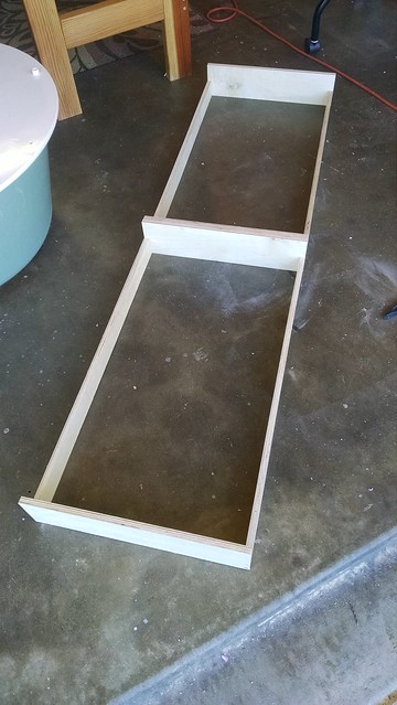
Some screwing-and-glueing left me with this frame:
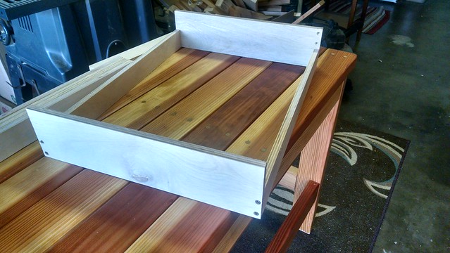
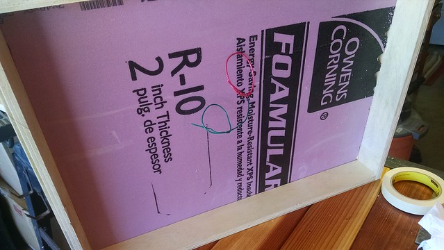
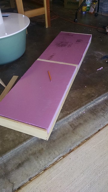
I am counting on the rigidity of the foam to shore up the frame without cross-members. It's already fairly rigid as is. Added the foam:
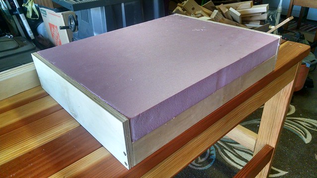
This makes a nice, lightweight module that is very strong. Pleased with the results. The two modules for the layout will be a bit longer, so I might add a cross-member if needed.
I can see myself using this method in the future to build a much larger, interlinked point-to-point layout. Really a fan of the lightweight simplicity of the design.
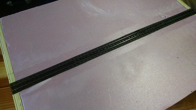
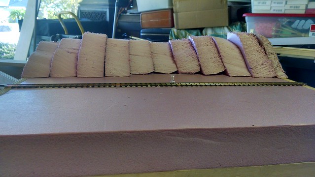
Then, I laid some track. Rail was soldered PCB sleepers at either end to have rock-solid alignment.
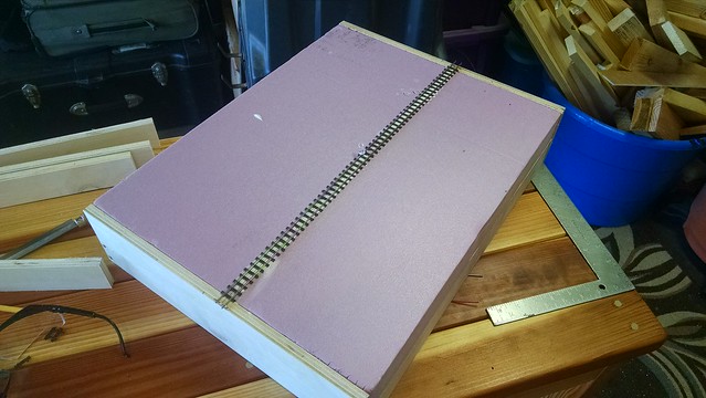
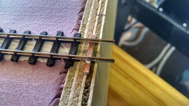
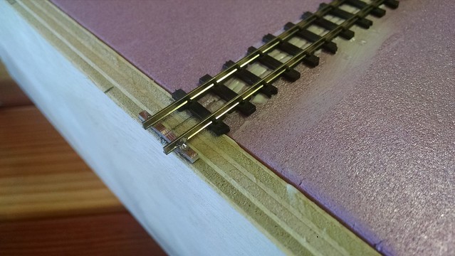
Even though this is a static module/diorama for now, I am building it to spec so it could link into a possible future modular setup. So, I dropped a pair of feeders. There is plenty of space between HOn30 ties to solder the feeders to the underside of the rail; that way, the feeders will essentially disappear when the track is ballasted.
The track was spray-bombed with cheap flat black paint in preparation for weathering. I'm going to try Joey Ricard's method using acrylics and powders, to see if the results are worth using on the full layout.
Another test-project for this module was using lateral stacking of the foam for landforms. I'm never really happy with the land contours I create when the foam is stacked one layer on top of another; I'm also never happy with the amount of dust I create carving the land profiles. So, I started by creating cardstock templates for each 2" cross-section of the hill.
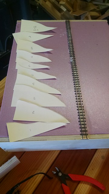
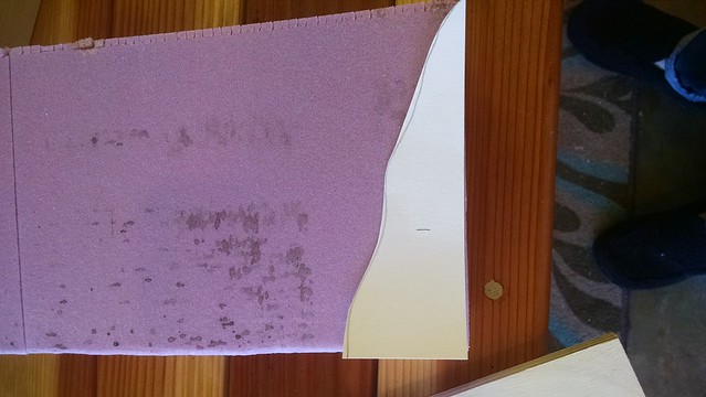
The sections were cut out using an old steak knife. Dry fit:

They were glued together in sections and clamped to dry.
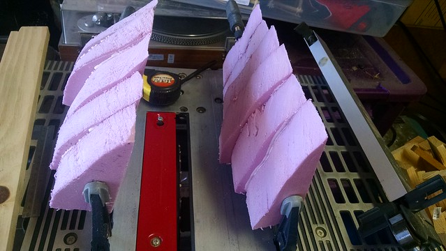
I will have to spend some time blending the cross-sections together, but overall I created a pleasing hill contour with less effort and dust than usual. Some of the larger "gaps" will be filled with stray foam pieces, or perhaps a few rock castings.
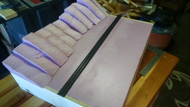
Most likely the flat area in front will be carved into a shallow, sloping ravine.
While working on the diorama, I decided to put together the benchwork for the main layout. I've arrived at a clamping method that satisfies my OCD need for perfect right-angles in my joinery.
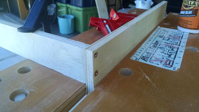
I lacked that same precision when fitting the foam, but luckily the more ragged edges can be placed towards the outer sides of the layout. Since there will be turnback curves there and no track interfaces, this should be OK. I'm really pleased with this construction method, as it yields very strong benchwork that is feather-light.
I have to put in an order for track and turnouts for the big layout soon, so while I am waiting for those to be delivered I can test out techniques on the module. See you next time! Be sure to "follow" this blog for updates in your email inbox.
No comments:
Post a Comment